Manage Software Load Balancer for SDN
Applies to: Azure Stack HCI, versions 22H2; Windows Server 2022, Windows Server 2019, Windows Server 2016
In this topic, learn how to manage Software Load Balancer (SLB) policies using Windows Admin Center after you deploy Software Defined Networking (SDN). SLBs are used to evenly distribute network traffic among multiple resources. SLB enables multiple servers to host the same workload, providing high availability and scalability. You can create load balancers for your workloads hosted on traditional VLAN networks (SDN logical networks) as well as for workloads hosted on SDN virtual networks. To learn more about SLB, see What is SLB for SDN?
Note
You need to deploy the SDN Network Controller and SLB components before you can create load balancer policies.
Create a new load balancer
You can create three types of SLBs:
Internal SLB - This is an internal load balancer used by internal cluster resources to reach internal load-balanced endpoints in an Azure Stack HCI cluster. The backend servers for this type of load balancer can belong to an SDN virtual network.
Public IP SLB - This is an external load balancer that is used to reach public load-balanced endpoints hosted in an HCI cluster. Before you create a public IP load balancer, you need to create a public IP address. The backend servers for this type of load balancer can belong to an SDN logical network (traditional VLAN network) or an SDN virtual network.
IP Address SLB - This is similar to the Public IP SLB. The difference between Public IP SLB and IP Address SLB is that the Public IP SLB creates a public IP resource that is then added to the load balancer. This is useful if you want to reserve that IP address for future use without it going back into the pool. The IP Address SLB assigns the IP address directly to the load balancer without creating a public IP resource. If you delete the load balancer, the IP address is returned to the pool.
To create an SLB, complete the following steps in Windows Admin Center:
- In Windows Admin Center, under All Connections, select the cluster you want to create the load balancer on.
- Under Tools, scroll down to Networking, and select Load Balancers.
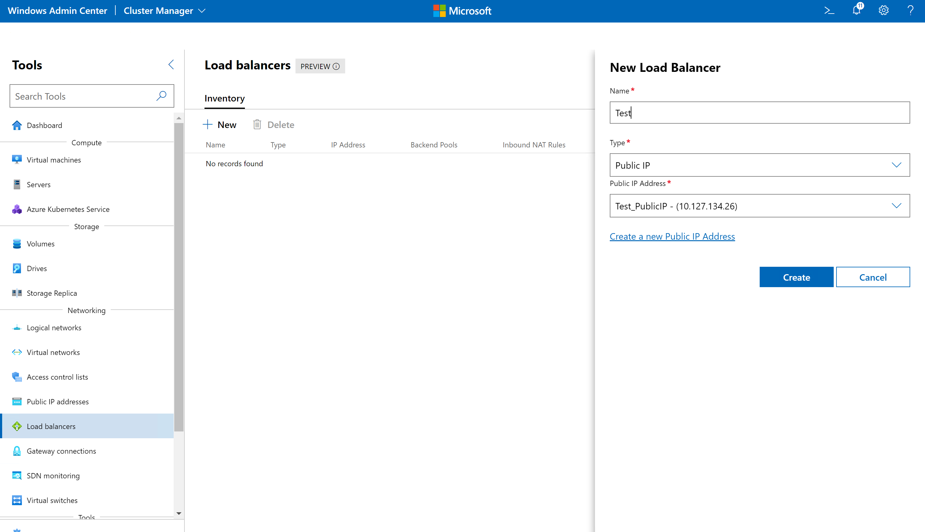
- Under Load Balancers, select the Inventory tab, then select New.
- Under New Load Balancers, enter a name for the load balancer
- Select the Type of Load Balancer. Type can be Public IP, GRE, or IP Address.
- If Type is Public IP, select a public IP Address or click on Create a new Public Address to create one. This is the external load balanced IP that will be visible to clients.
- If Type is Internal, select a virtual network, a network subnet, and a Private IP address from the virtual network subnet. This IP address is the internal load-balanced IP that will be visible to internal clients.
- If Type is IP Address, you can select if the load balancer will be used for external load balancing (Public VIP) or internal load balancing (Private VIP).
- If you select Public VIP, select a public SDN logical network, logical network subnet, and a public VIP IP address from that subnet.
- If you select Private VIP, select an SDN logical network, logical network subnet, and a private VIP IP address from that subnet.
- Click Create to create the load balancer.
Create a Public IP Address SLB
A public IP address must be created first if you are creating a Public IP Address SLB.
- In Windows Admin Center, under All Connections, select the cluster you want to create the public IP address on.
- Under Tools, scroll down to Networking, and select Public IP addresses.
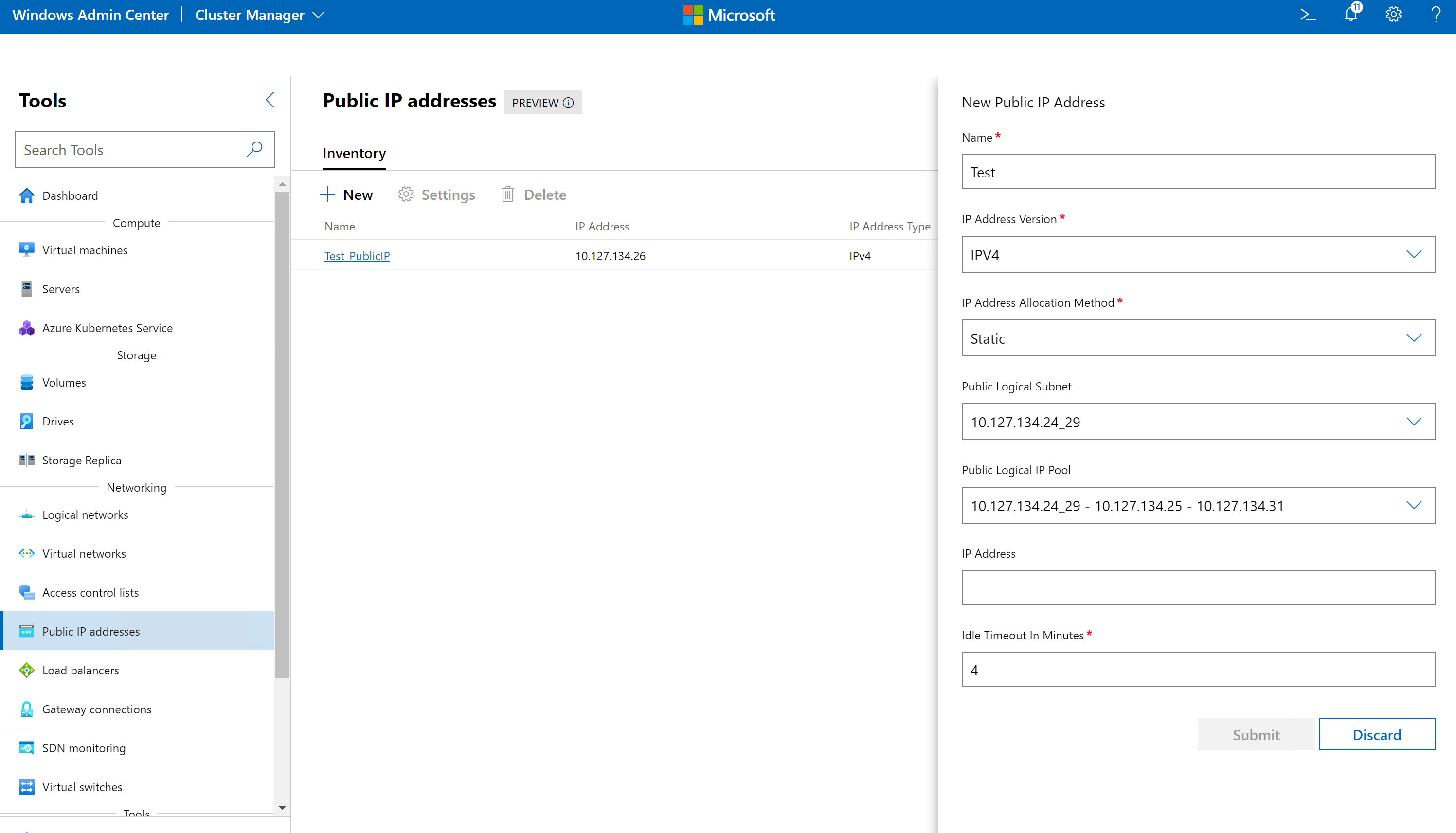
- Under Public IP addresses, select the Inventory tab, then select New.
- Under New Public IP address, enter a name for the address.
- Select the IP Address Version (IPv4/IPv6).
- Select the IP Address Allocation Method (Static/Dynamic).
- If IP Address Allocation Method is Static, select a Public Logical Subnet, select a Public Logical IP Pool from that subnet, and select an IP address from the Logical pool.
- Provide an Idle Timeout value for the IP address in minutes. This specifies the timeout for a TCP idle connection. The value can be set between 4 and 30 minutes. The default is 4 minutes.
- Click Submit to configure the IP address.
Create a front IP configuration
After you create a load balancer, you need to define the front IP configuration for the load balancer. Front IP configuration is the front-end IP used for your load balancer. By default, when you create a load balancer, a front IP configuration is automatically created with the load balancer IP address.
- In Windows Admin Center, under All Connections, select the cluster you want to create the load balancer on.
- Under Tools, scroll down to Networking, and select Load Balancers.
- Under Load Balancers, select the Inventory tab, and click on the load balancer for which you want to add the front IP configuration.
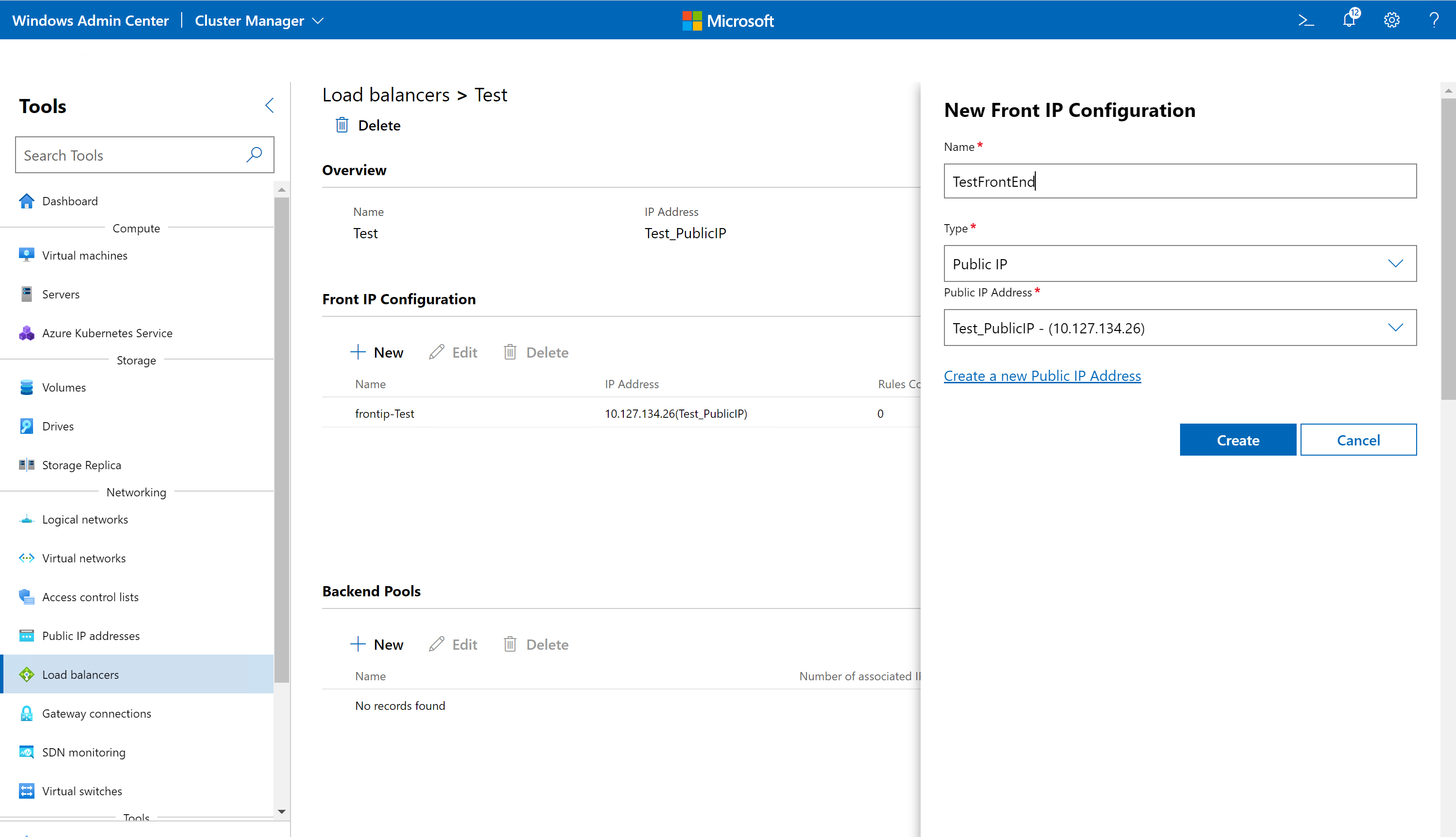
- In the Front IP Configuration section, click New.
- Under New Front IP Configuration, enter a name.
- Set the Type as Public IP if Load Balancer type is Public IP. Select Type as Internal if Load Balancer Type is Internal. Select Type as IP Address if Load Balancer type is IP Address.
- If type is Public IP, Select a Public IP Address.
- If type is Internal, select Virtual Network, Virtual Network Subnet and Private IP address.
- If type is IP Address, select if the load balancing is for public networks or private networks and then select corresponding logical network, logical network subnets and IP address.
- Click Create to create the front IP configuration.
Create a backend pool
A backend pool represents the list of IP addresses that can receive network traffic coming from the front-end IPs. The load balancer handles incoming traffic via the frontend IPs and distributes them to backend IPs based on the load balancing policy.
- In Windows Admin Center, under All Connections, select the cluster you want to create the load balancer on.
- Under Tools, scroll down to Networking, and select Load Balancers.
- Under Load Balancers, select the Inventory tab, and click on the load balancer for which you want to add the front IP configuration.
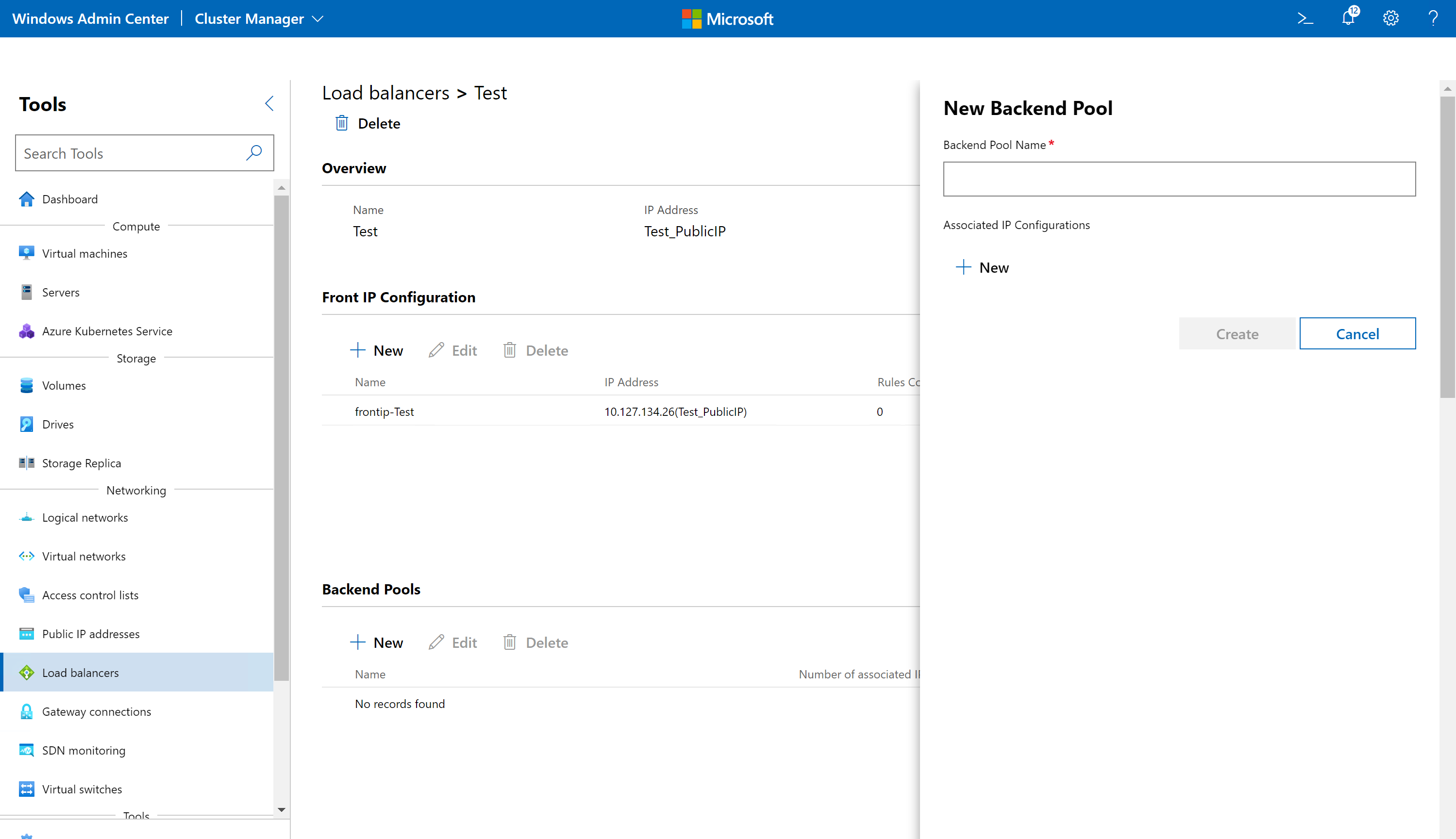
- In the Backend Pools section, click New.
- Under New Backend Pool, enter a name.
- In the Associated IP Configurations, click New.
- Select a Network Interface and a Target Network IP configuration on the network interface. Click Submit.
- Add more IP configurations as needed. Each of these will serve as a backend pool member for a front IP configuration.
- Click Create.
Create an inbound NAT rule
An inbound NAT rule configures the load balancer to apply Network Address Translation (NAT) to inbound traffic. This is used for forwarding external traffic to a specific virtual machine (VM). If you want to configure load balancing, you do not need to setup inbound NAT rules.
- In Windows Admin Center, under All Connections, select the cluster you want to create the load balancer on.
- Under Tools, scroll down to Networking, and select Load Balancers.
- Under Load Balancers, select the Inventory tab, and click on the load balancer for which you want to add the Inbound NAT rule.
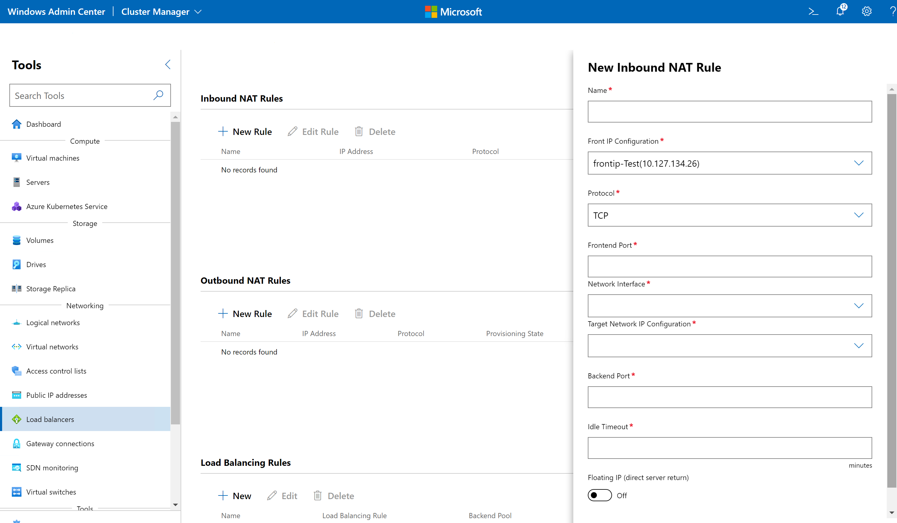
- In the Inbound NAT Rules section, click New.
- Under New Inbound NAT rule, enter a name.
- In the Front IP Configurations, select a frontend IP address for the load balancer.
- Select a protocol. Accepted values are TCP, UDP and All. This indicates the inbound transport protocol for the external endpoint.
- Enter a value for the Frontend Port. This is the port for the external endpoint. Possible values range between 1 and 65535, inclusive.
- Select a Network Interface and Target Network IP Configuration. Traffic destined to the front end IP will be forwarded to this network interface.
- Enter a value for the Backend Port. This is the port for the internal endpoint. Possible values range between 1 and 65535, inclusive.
- Provide an Idle Timeout value. This indicates the timeout for the TCP idle connection in the inbound direction, i.e. a connection initiated by an internet client to a frontend IP. The value can be set between 4 and 30 minutes.
- Select whether you want to enable Floating IP.
- Click Create.
Create an outbound NAT rule
An outbound NAT rule configures the load balancer to forward VM network traffic from the SDN virtual or logical network to external destinations using network address translation (NAT). This is useful when you want to configure your internal network resources to have internet access. If you want to configure load balancing, you do not need to setup outbound NAT rules.
- In Windows Admin Center, under All Connections, select the cluster you want to create the load balancer on.
- Under Tools, scroll down to Networking, and select Load Balancers.
- Under Load Balancers, select the Inventory tab, and click on the load balancer for which you want to add the Outbound NAT rule.
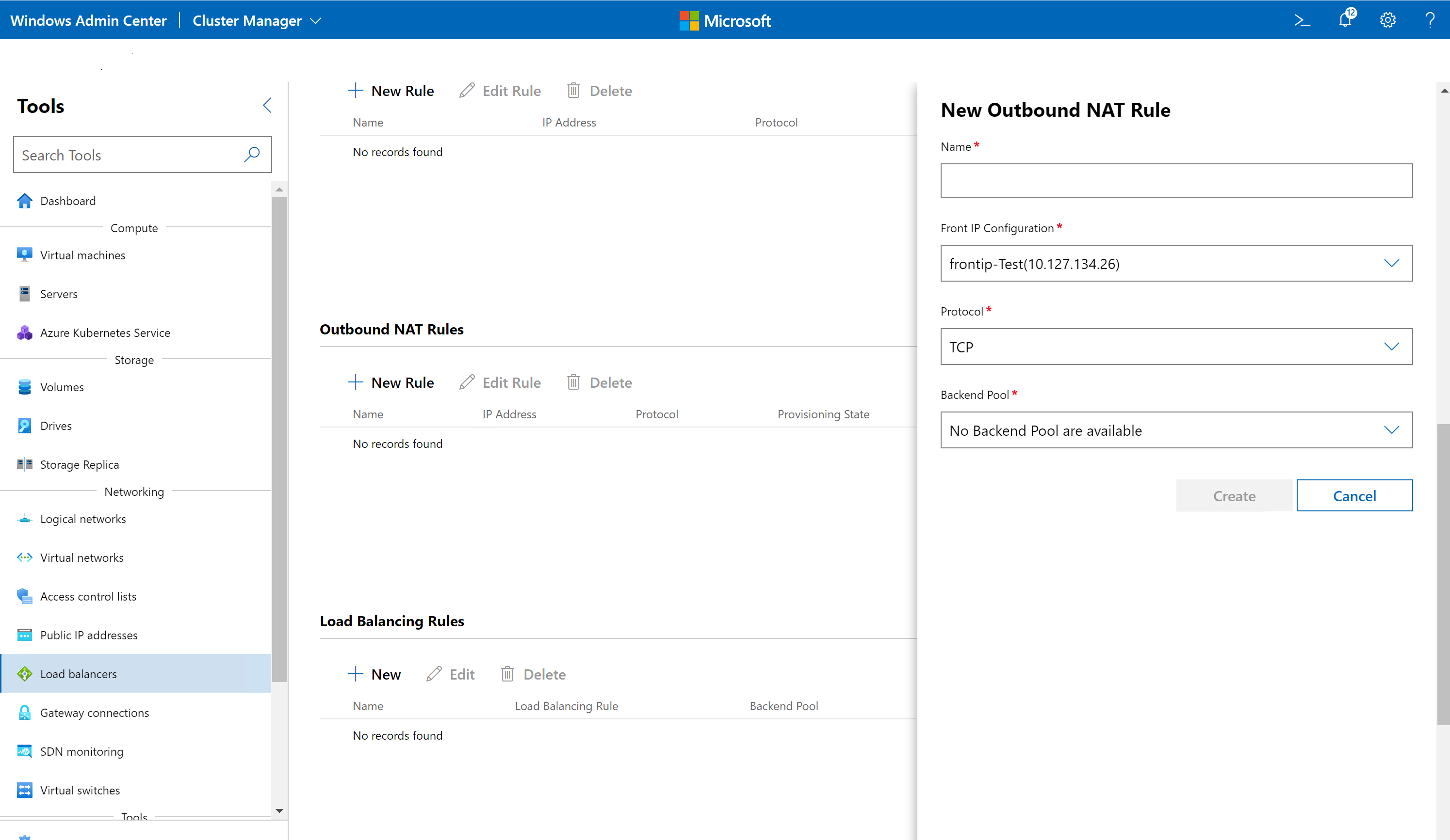
- In the Outbound NAT Rules section, click New.
- Under New Outbound NAT rule, enter a name.
- In the Front IP Configurations, select a frontend IP address for the load balancer. This is the IP address to which the outbound packets will be routed to.
- Select a Protocol. Accepted values are TCP, UDP, and All. This indicates the transport protocol for outbound traffic. For transparent outbound traffic, specify All.
- Select a Backend Pool. This is the pool of network interfaces where outbound traffic originates.
- Click Create.
Create a load balancing rule
A load balancing rule configures the load balancer to evenly distribute tenant network traffic among multiple resources. This enables multiple servers to host the same workload, providing high availability and scalability.
Set Session Persistence using the following procedure. Session persistence specifies the load balancing distribution type to be used by the load balancer. The load balancer uses a distribution algorithm that is a 5-tuple (source IP, source port, destination IP, destination port, and protocol type) hash to map traffic to available servers. This provides stickiness within a transport session, which routes requests for a specific session to the same physical server that serviced the first request for that session. Packets in the same TCP or UDP session will be directed to the same backend instance behind the frontend IP. When the client closes and re-opens the connection or starts a new session from the same source IP, the source port changes and may cause the traffic to go to a different backend IP.
- In Windows Admin Center, under All Connections, select the cluster you want to create the load balancer on.
- Under Tools, scroll down to Networking, and select Load Balancers.
- Under Load Balancers, select the Inventory tab, and click on the load balancer for which you want to add the load balancing rule.
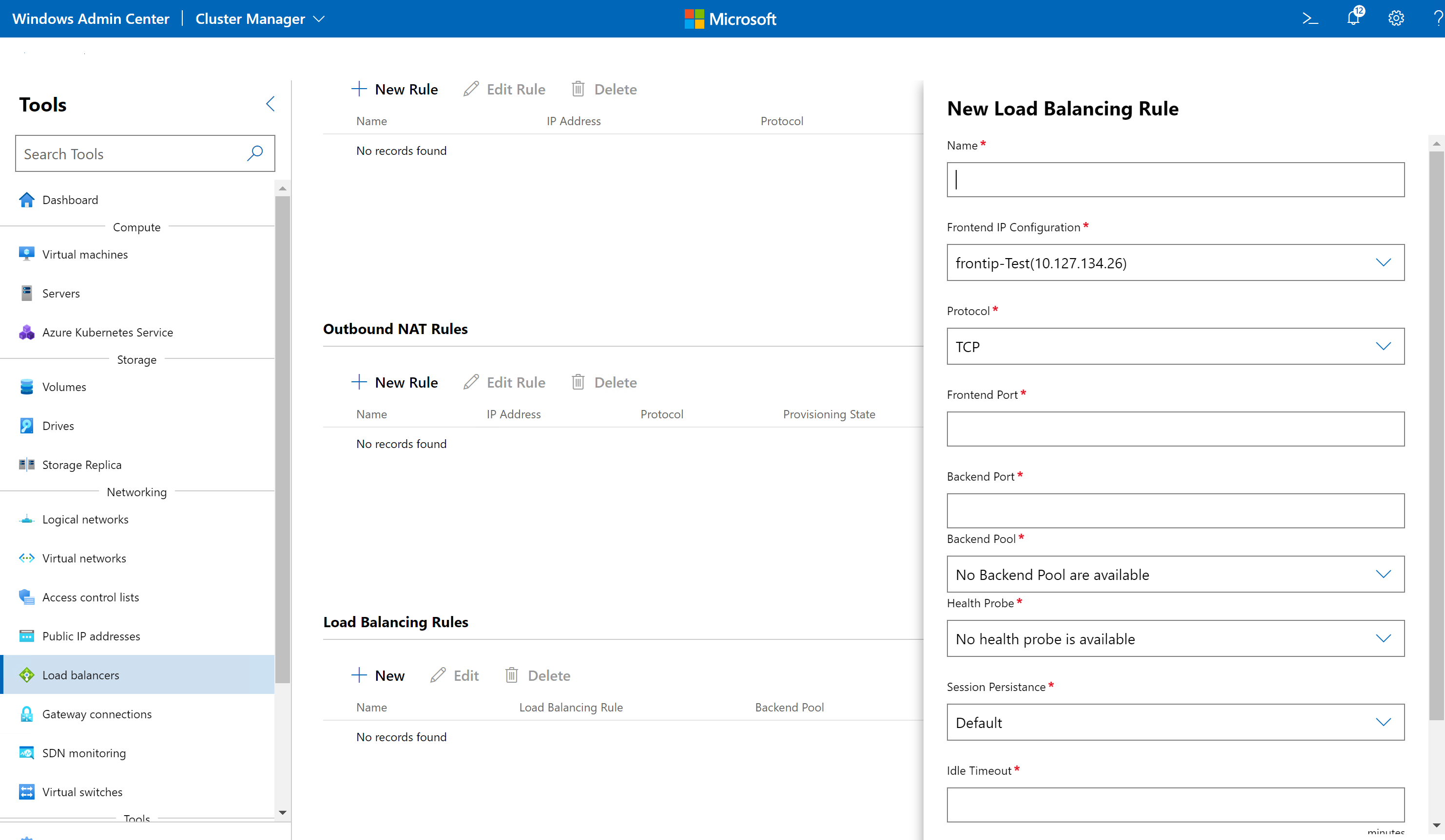
- In the Load Balancing Rules section, click New.
- Under New Load Balancing rule, enter a name.
- In the Front IP Configurations, select a frontend IP address of the load balancer.
- Select a Protocol. Accepted values are TCP, UDP and All. This indicates the inbound transport protocol for the frontend IP.
- Enter a value for the Frontend Port. This is the port for the frontend IP. Possible values range between 1 and 65535, inclusive.
- Enter a value for the Backend Port. This is the port for the internal endpoint. Possible values range between 1 and 65535, inclusive.
- Select a Backend Pool. Inbound traffic is load balanced across IPs in the backend pool.
- Select a Health Probe. See next procedure for information.
- Select a value for Session Persistence.
- Default – The load balancer is configured to use a 5-tuple (source IP, source port, destination IP, destination port, and protocol type) hash to map traffic to available servers.
- SourceIP – The load balancer is configured to use a 2-tuple (source IP and destination IP) hash to map traffic to available servers.
- SourceIPProtocol – The load balancer is configured to use a 3-tuple (source IP, destination IP, and protocol) hash to map traffic to available servers.
- Provide an Idle Timeout value. This indicates the timeout for the TCP idle connection in the inbound direction, such as a connection initiated by an internet client to a frontend IP. The value can be set between 4 and 30 minutes.
- Select whether you want to enable Floating IP. In this case, the frontend IP will be configured on one of the backend pool members, and any traffic to the frontend IP will be sent directly to that backend pool member. This is useful for guest clustering scenarios that work through a floating IP address set on the active instance of the cluster. The health probe will determine which backend IP is active, and the load balancer will set the front end IP on that backend pool member.
- Click Create.
Create a health probe
A health probe is used by the load balancer to determine the health state of the backend pool members. If a backend pool member is not healthy, it doesn't receive traffic from the load balancer.
- In Windows Admin Center, under All Connections, select the cluster you want to create the load balancer on.
- Under Tools, scroll down to Networking, and select Load Balancers.
- Under Load Balancers, select the Inventory tab, and click on the load balancer for which you want to add the health probe.
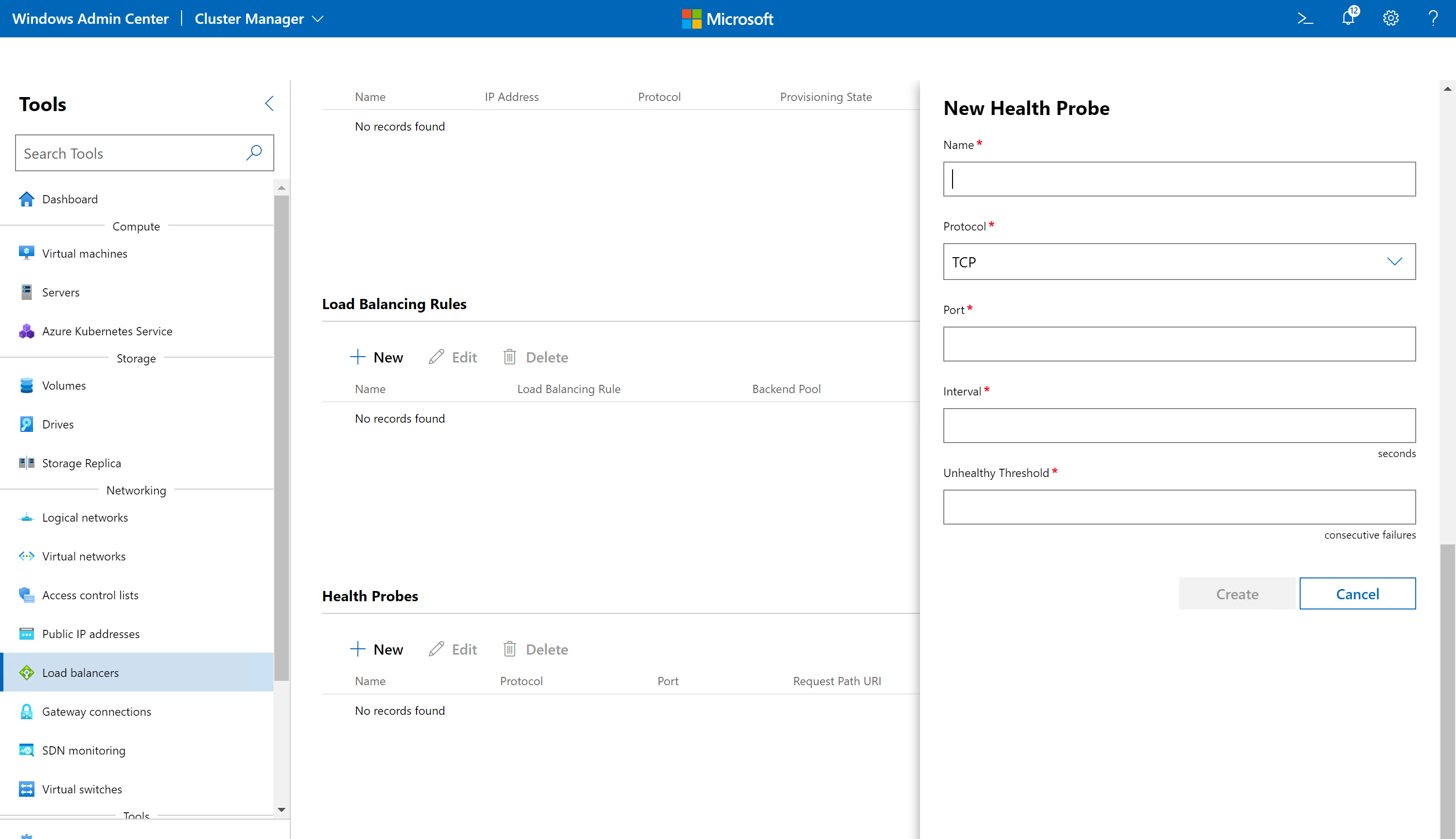
- In the Health Probes section, click New.
- Under New Health Probe, enter a name.
- Select a protocol. Accepted values are TCP, and HTTP. If TCP is specified, a received acknowledgment (ACK) is required for the probe to be successful. If HTTP is specified, a 200 (OK) response from the specified URI is required for the probe to be successful.
- Provide value for Port. This is the port for communicating with the probe. Possible values range from 1 to 65535, inclusive.
- If the protocol is HTTP, provide a Request Path URI. This is the URI path in the backend VM that will be queried to get the health status of the VM.
- Provide the Interval in seconds. This indicates how frequently to probe the endpoint for health status.
- Provide the Unhealthy Threshold value. This indicates the timeout period (in seconds) without any response, upon which the load balancer will stop sending further traffic to the backend VM. The minimum value is 11 seconds.
- Click Create.
View and change load balancer details
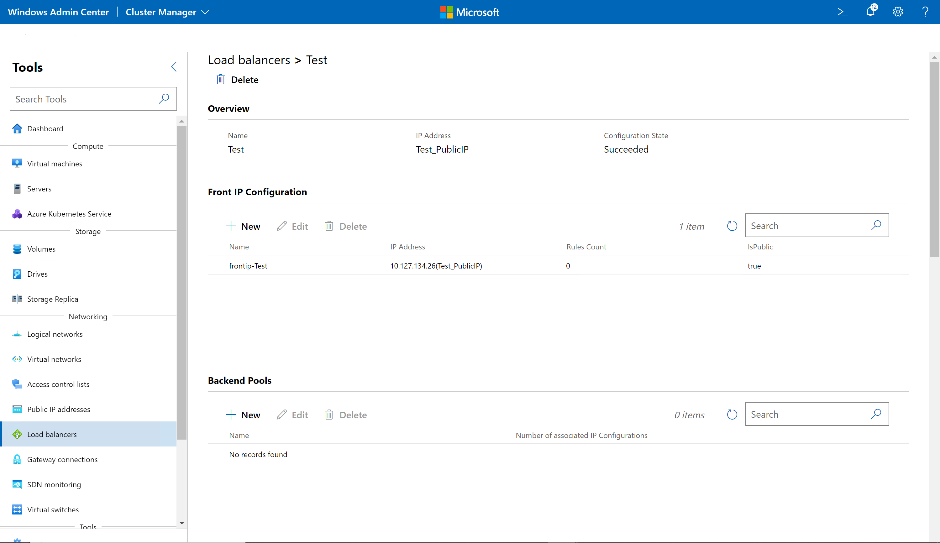
You can view detailed information for a specific load balancer from its dedicated page.
- In Windows Admin Center, under Tools, scroll down and select Load Balancers.
- Select the Inventory tab on the right, then select a load balancer. On the subsequent page, you can do the following:
- View the details of the load balancer.
- View, add, change, or remove a front IP configuration.
- View, add, change, or remove a backend pool.
- View, add, change, or remove inbound NAT rules.
- View, add, change, or remove outbound NAT rules.
- View, add, change, or remove load balancing rules.
- View, add, change, or remove health probes.
Delete a load balancer
You can delete a load balancer if you no longer need it.
- Under Tools, scroll down and select Load Balancers.
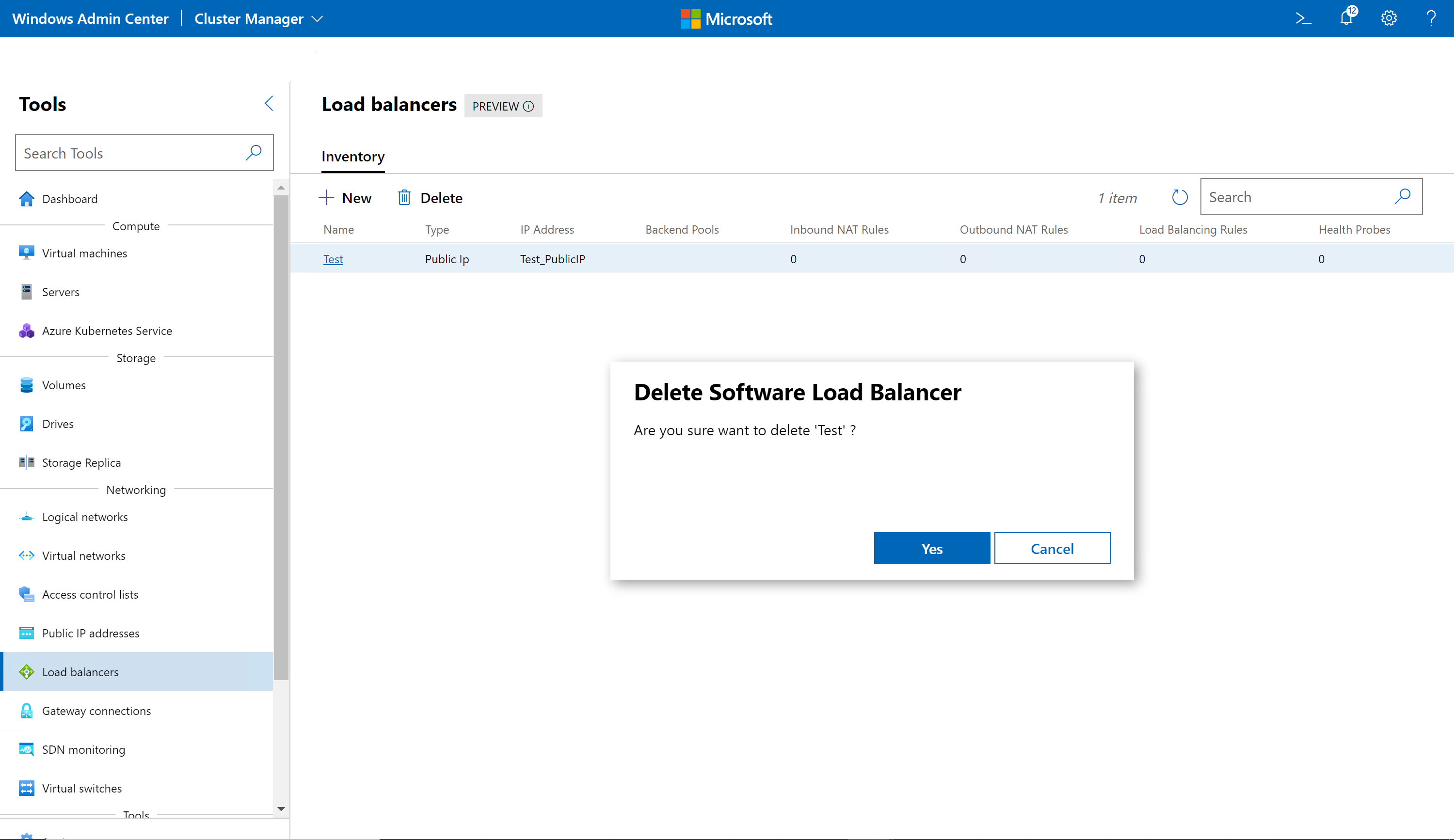
- Click the Inventory tab on the right, then select a load balancer. Click Delete.
- On the confirmation dialog, click Yes. Click Refresh to check that the load balancer has been deleted.
