Note
Access to this page requires authorization. You can try signing in or changing directories.
Access to this page requires authorization. You can try changing directories.
This article provides Azure Stack Hub storage infrastructure information to help you decide how to integrate Azure Stack Hub into your existing networking environment. After providing a general discussion of extending your datacenter, the article presents two different scenarios. You can connect to a Windows file storage server. You can also connect to a Windows iSCSI server.
Overview of extending storage to Azure Stack Hub
There are scenarios where having your data located in the public cloud isn't enough. Perhaps you have a compute-intensive virtualized database workload that's sensitive to latencies, and the round-trip time to the public cloud could affect performance of the database workload. Perhaps there's data on-premises, held on a file server, NAS, or iSCSI storage array, which needs to be accessed by on-premises workloads, and needs to reside on-premises to meet regulatory or compliance goals. These scenarios show why having data reside on-premises remains important for many organizations.
So, why not just host that data in storage accounts on Azure, or inside virtualized file servers, running on the Azure Stack Hub system? Well, unlike in Azure, Azure Stack Hub storage is finite. The capacity you have available for your usage depends entirely on the per-node capacity you choose to purchase, in addition to the number of nodes you have. And because Azure Stack Hub is a hyper-converged solution, if you wish to grow your storage capacity to meet usage demands, you also need to grow your compute footprint through the addition of nodes. This requirement can be potentially cost prohibitive, especially if the need for extra capacity is for cold, archival storage that could be added for low cost outside of the Azure Stack Hub system.
This requirement brings you to the scenario that you cover in the next section. How can you connect Azure Stack Hub systems, virtualized workloads running on the Azure Stack Hub, simply and efficiently, to storage systems outside of the Azure Stack Hub, accessible via the network?
Design for extending storage
The following diagram depicts a scenario where a single virtual machine running a workload connects to and utilizes external storage (to the VM, and the Azure Stack Hub itself) for purposes of data reading and writing. For this article, you focus on simple retrieval of files, but you can expand this example for more complex scenarios, such as the remote storage of database files.
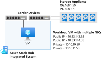
In the diagram, you see that the VM on the Azure Stack Hub system is deployed with multiple NICs. From both a redundancy, but also a storage best practice, it's important to have multiple paths between target and destination. Where things become more complex, are where VMs in Azure Stack Hub have both public and private IPs, just like in Azure. If the external storage needs to reach the VM, it can only do so via the public IP, as the private IPs are primarily used within the Azure Stack Hub systems, within vNets and the subnets. The external storage can't communicate with the private IP space of the VM, unless it passes through a site-to-site VPN, to punch into the vNet itself. So, for this example, focus on communication via the public IP space. One thing to notice with the public IP space in the diagram, is that there are two different public IP pool subnets. By default, Azure Stack Hub requires just one pool for public IP address purposes, but something to consider, for redundant routing, is to add a second. However, at this time, it isn't possible to select an IP address from a specific pool, so you might indeed end up with VMs with public IPs from the same pool across multiple virtual network cards.
For the purposes of this discussion, assume that the routing between the border devices and the external storage is taken care of, and traffic can traverse the network appropriately. For this example, it doesn't matter if the backbone is 1 GbE, 10 GbE, 25 GbE, or even faster. However, this choice would be important to consider as you plan for your integration, to address the performance needs of any applications accessing this external storage.
Connect to a Windows Server iSCSI Target
In this scenario, you deploy and configure a Windows Server 2019 virtual machine on Azure Stack Hub and prepare it to connect to an external iSCSI Target, which also runs Windows Server 2019. Where appropriate, you enable key features such as MPIO, to optimize performance and connectivity between the VM and external storage.
Deploy the Windows Server 2019 VM on Azure Stack Hub
From your Azure Stack Hub administration portal, assuming you register the system correctly and connect it to the marketplace, select Marketplace Management. If you don't already have a Windows Server 2019 image, select Add from Azure and then search for Windows Server 2019. Add the Windows Server 2019 Datacenter image.
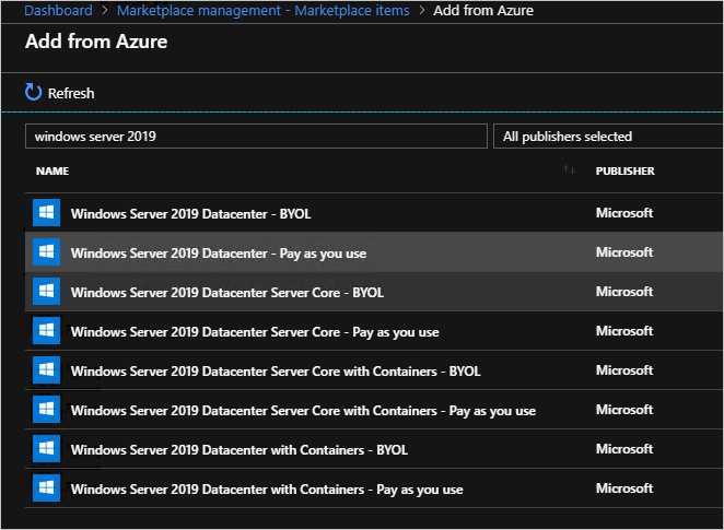
Downloading a Windows Server 2019 image can take some time.
After you add a Windows Server 2019 image to your Azure Stack Hub environment, sign in to the Azure Stack Hub user portal.
After you sign in to the Azure Stack Hub user portal, ensure you have a subscription to an offer that allows you to provision IaaS resources (Compute, Storage, and Network).
After you get a subscription, back on the dashboard in the Azure Stack Hub user portal, select Create a resource, select Compute, and then select the Windows Server 2019 Datacenter gallery item.
On the Basics blade, enter the following information:
Name: VM001
Username: localadmin
Password and Confirm password: <password of your choice>
Subscription: <subscription of your choice, with compute/storage/network resources>.
Resource group: storagetesting (create new)
Select OK
On the Choose a size blade, select a Standard_F8s_v2 and select Select.
On the Settings blade, select the Virtual network. In the Create virtual network blade, set the address space to 10.10.10.0/23 and update the Subnet address range to 10.10.10.0/24. Select OK.
Select the Public IP address. In the Create public IP address blade, select the Static radio button.
On the Select public inbound ports dropdown, select RDP (3389).
Leave the other defaults and select OK.
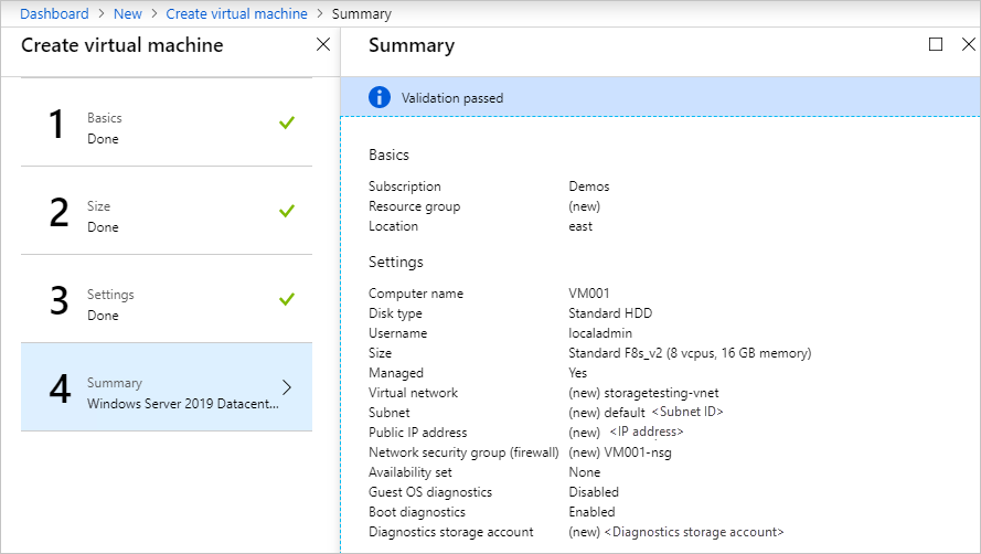
Read the summary, wait for validation, and then select OK to begin the deployment. The deployment should complete in about 10 minutes.
After the deployment completes, under Resource select the virtual machine name, VM001 to open Overview.
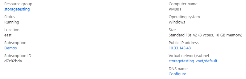
Under DNS name, select Configure and provide a DNS name label, vm001 and select Save, then select VM001.
On the right-hand side of the overview blade, select storagetesting-vnet/default under the Virtual network/subnet text.
Within the storagetesting-vnet blade, select Subnets and then +Subnet. In the new Add Subnet blade, enter the following information, and then select OK:
Name: subnet2
Address range (CIDR block): 10.10.11.0/24
Network Security Group: None
Route table: None
After saving, select VM001.
From the left side of the overview, select Networking.
Select Attach network interface, and then select Create network interface.
On Create network interface, enter the following information:
Name: vm001nic2
Subnet: Ensure subnet is 10.10.11.0/24
Network security group: VM001-nsg
Resource group: storagetesting
After you attach the network interface, select VM001 and select Stop to shut down the VM.
After the VM is stopped (deallocated), on the left side of the overview, select Networking, select Attach network interface, and then select vm001nic2. Select OK. The additional NIC is added to the VM in a few moments.
Still on the Networking blade, select the vm001nic2 tab, and then select Network Interface:vm001nic2.
On the vm001nic interface blade, select IP configurations, and in the center of the blade, select ipconfig1.
On the ipconfig1 settings blade, select Enabled for Public IP address and select Configure required settings. Select Create new, enter vm001nic2pip for the name, select Static, and select OK. Select Save.
After you save the settings, return to the VM001 overview, and select Start to start your configured Windows Server 2019 VM.
After the VM starts, establish an RDP session into the VM001.
After you connect inside the VM, open CMD (as administrator) and enter hostname to retrieve the computer name of the OS. It should match VM001. Make a note of this name for later.
Configure second network adapter on Windows Server 2019 VM on Azure Stack Hub
By default, Azure Stack Hub assigns a default gateway to the first (primary) network interface attached to the virtual machine. Azure Stack Hub doesn't assign a default gateway to additional (secondary) network interfaces attached to a virtual machine. Therefore, you can't communicate with resources outside the subnet that a secondary network interface is in, by default. However, secondary network interfaces can communicate with resources outside their subnet, though the steps to enable communication are different for different operating systems.
If you don't already have a connection open, establish an RDP connection into VM001.
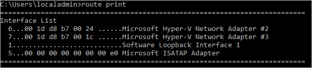
Open CMD as administrator and run route print which should return the two interfaces (Hyper-V Network Adapters) inside this VM.
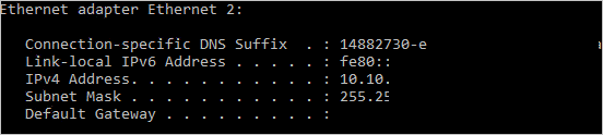
Run ipconfig to see which IP address is assigned to the secondary network interface. In this example, 10.10.11.4 is assigned to interface 6. No default gateway address is returned for the secondary network interface.
To route all traffic destined for addresses outside the subnet of the secondary network interface to the gateway for the subnet, run the following command from the CMD:.
route add -p 0.0.0.0 MASK 0.0.0.0 <ipaddress> METRIC 5015 IF <interface>The
<ipaddress>is the .1 address of the current subnet, and<interface>is the interface number.
To confirm the added route is in the route table, enter the route print command.

You can also validate outbound communication by running a ping command:
ping 8.8.8.8 -S 10.10.11.4
The-Sflag allows you to specify a source address, in this case, 10.10.11.4 is the IP address of the NIC that now has a default gateway.Close CMD.
Configure the Windows Server 2019 iSCSI Target
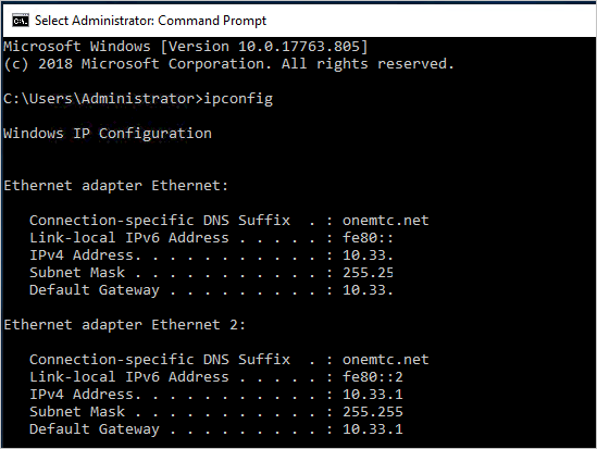
In this scenario, you validate a configuration where the Windows Server 2019 iSCSI Target is a virtual machine running on Hyper-V, outside of the Azure Stack Hub environment. You configure this virtual machine with eight virtual processors, a single VHDX file, and most importantly, two virtual network adapters. In an ideal scenario, these network adapters have different routable subnets, but in this validation, they have network adapters on the same subnet.
For your iSCSI Target server, you can use Windows Server 2016 or Windows Server 2019, physical or virtual, running on Hyper-V, VMware, or an alternative appliance of your choice, such as a dedicated physical iSCSI SAN. The key focus is connectivity into and out of the Azure Stack Hub system. However, having multiple paths between the source and destination is preferable, as it provides additional redundancy, and it allows the use of more advanced capabilities to drive increased performance, such as MPIO.
Update your Windows Server 2019 iSCSI Target with the latest cumulative updates and fixes, and reboot if necessary, before proceeding with the configuration of file shares.
After updating and rebooting, you can now configure this server as an iSCSI Target.
Open Server Manager and select Manage, and then select Add Roles and Features.
Once opened, select Next, select Role-based or feature-based installation, and proceed through the selections until you reach the Select server roles page.
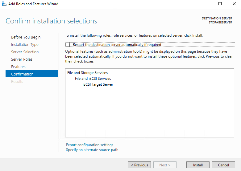
Expand File and Storage Services, expand File & iSCSI Services, and select the iSCSI Target Server box. Accept any popup prompts to add new features, and then proceed through to completion.
Once completed, close Server Manager.
Open File Explorer, go to C:\ and create a new folder named iSCSI.
Reopen Server Manager and select File and Storage Services from the left-hand menu.
Select iSCSI and select the "To create an iSCSI virtual disk, start the New iSCSI Virtual Disk Wizard" link on the right pane. A dialog box opens.
On the Select iSCSI virtual disk location page, select the radio button for Type a custom path and browse to your C:\iSCSI and select Next.
Enter iSCSIdisk1 as the name for the iSCSI virtual disk and optionally, add a description, and then select Next.
Set the size of the virtual disk to 10GB, select Fixed size, and select Next.
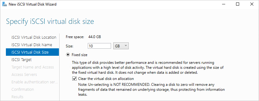
Since this is a new target, select New iSCSI target and select Next.
On the Specify target name page, enter TARGET1 and select Next.
On the Specify access servers page, select Add. This step opens a dialog to enter specific initiators that are authorized to connect to the iSCSI Target.
In the Add initiator ID window, select Enter a value for the selected type and under Type ensure IQN is selected in the drop-down menu. Enter iqn.1991-05.com.microsoft:<computername> where <computername> is the computer name of VM001 and then select Next.
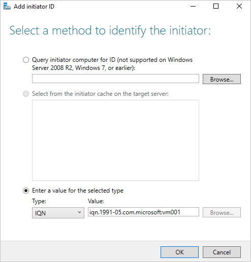
On the Enable Authentication page, leave the boxes blank, and then select Next.
Confirm your selections and select Create, and then close. You should see your iSCSI virtual disk created in Server Manager.
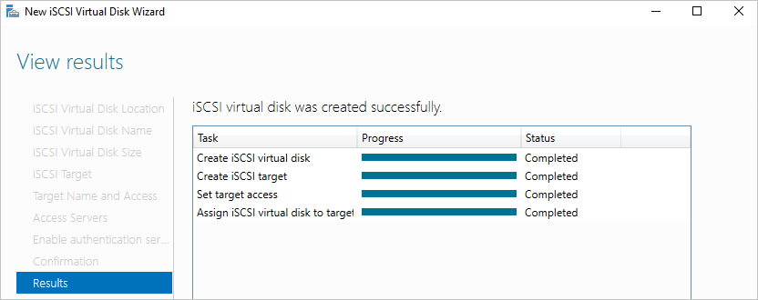
Configure the Windows Server 2019 iSCSI Initiator and MPIO
To set up the iSCSI Initiator, first, sign in to the Azure Stack Hub user portal on your Azure Stack Hub system and go to the overview page for VM001.
Establish an RDP connection to VM001. Once connected, open Server Manager.
Select Add roles and features, and accept the defaults until you reach the Features page.
On the Features page, add Multipath I/O and select Next.
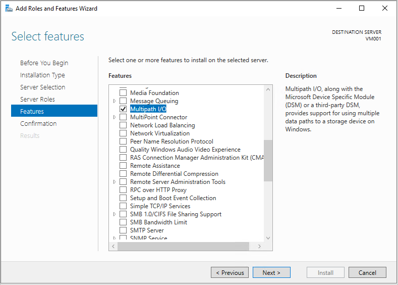
Select the Restart the destination server automatically if required box and select Install, and then select Close. A reboot is most likely required, so once completed, reconnect to VM001.
Back in Server Manager, wait for the MPIO install to complete, select close, and then select Tools and select MPIO.
Select the Discover Multi-Paths tab, and select the box to Add support for iSCSI devices and select Add, and then select Yes to reboot VM001. If you don't receive a window, select OK, and then reboot manually.
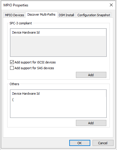
Once rebooted, establish a new RDP connection to VM001.
Once connected, open Server Manager, select Tools and select iSCSI Initiator.
When a Microsoft iSCSI window pops up, select Yes to allow the iSCSI service to run by default.
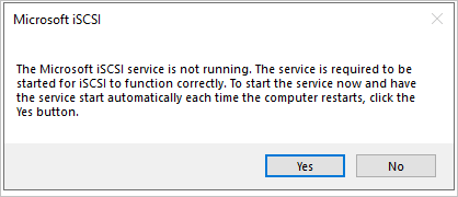
In the iSCSI Initiator properties window, select the Discovery tab.
You add two targets, so first select the Discover Portal button.
Enter the first IP address of your iSCSI Target server, and select Advanced.
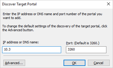
In the Advanced Settings window, select the following, and then select OK.
Local adapter: Microsoft iSCSI Initiator.
Initiator IP: 10.10.10.4.
Back in the Discover Target Portal window, select OK.
Repeat the process with the following values:
IP address: Your second iSCSI Target IP address.
Local adapter: Microsoft iSCSI Initiator.
Initiator IP: 10.10.11.4.
Your target portals should look like this, with your own iSCSI Target IPs under the Address column.
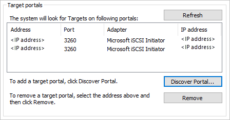
Back on the Targets tab, select your iSCSI Target from the middle of the window, and select Connect.
In the Connect to target window, select the Enable multi-path box, and select Advanced.
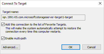
Enter the following information and select OK. In the Connect to Target window, select OK.
- Local adapter: Microsoft iSCSI Initiator.
- Initiator IP: 10.10.10.4.
- Target portal IP: <your first iSCSI Target IP / 3260>.
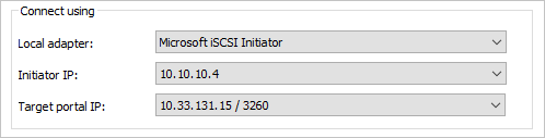
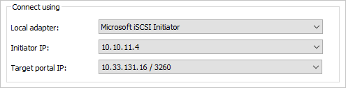
Repeat the process for the second initiator and target combination.
- Local adapter: Microsoft iSCSI Initiator.
- Initiator IP: 10.10.11.4.
- Target portal IP: <your second iSCSI Target IP / 3260>.
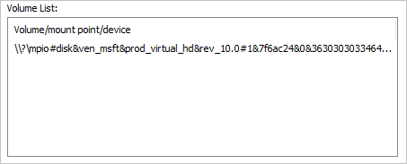
Select the Volumes and Devices tab, and then select Auto Configure. You see an MPIO volume presented:
Back on the Targets tab, select Devices and you see two connections to the single iSCSI VHD you created earlier.
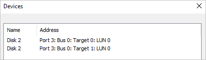
Select the MPIO button to see more information about the load-balancing policy and paths.
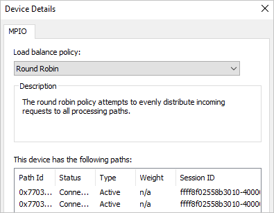
Select OK three times to exit the windows and the iSCSI Initiator.
Open Disk Management (diskmgmt.msc) and you're prompted with an Initialize Disk window.
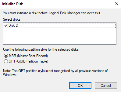
Select OK to accept the defaults. Then scroll down to the new disk, right-click, and select New Simple Volume.
Walk through the wizard, accepting the defaults. Change the Volume label to iSCSIdisk1 and then select Finish.
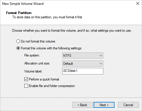
The drive is then formatted and presented with a drive letter.
Open File Explorer and select This PC to see your new drive attached to VM001.
Testing external storage connectivity
To validate communication and run a rudimentary file copy test, first, sign in to the Azure Stack Hub user portal on your Azure Stack Hub system and go to the overview page for VM001.
Select Connect to establish an RDP connection to VM001.
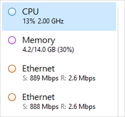
Open Task Manager, select the Performance tab, and then snap the window to the right-hand side of the RDP session.
Open Windows PowerShell ISE as administrator and snap it to the left-hand side of the RDP session. On the right-hand side of the ISE, close the Commands pane, and select the Script button, to expand the white script pane at the top of the ISE window.
In this VM, there are no native PowerShell modules to create a VHD, which you use as a large file to test the file transfer to the iSCSI Target. In this case, run DiskPart to create a VHD file. In the ISE, run the following steps:
Start-Process DiskpartA new CMD window opens. Enter the following command:
Create vdisk file="c:\\test.vhd" type=fixed maximum=5120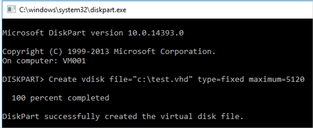
This process takes a few moments. When it's done, open File Explorer and go to C:\ - you see the new test.vhd file, and a size of 5 GB.
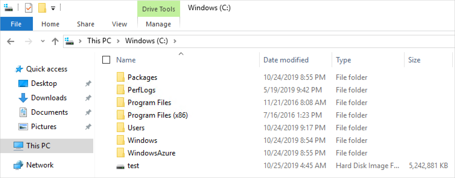
Close the CMD window, and return to the ISE. Enter the following command in the script window. Replace F:\ with the iSCSI Target drive letter that you applied earlier.
Copy-Item "C:\\test.vhd" -Destination "F:\\"Select the line in the script window, and press F8 to run.
While the command is running, watch the two network adapters and see the transfer of data taking place across both network adapters in VM001. You should also notice that each network adapter shares the load evenly.
This scenario highlights the connectivity between a workload running on Azure Stack Hub, and an external storage array, in this case, a Windows Server-based iSCSI Target. This scenario isn't designed to be a performance test, nor be reflective of the steps you'd need to perform if you were using an alternative iSCSI-based appliance. However, it does highlight some of the core considerations you'd make when deploying workloads on Azure Stack Hub, and connecting them to storage systems outside of the Azure Stack Hub environment.
Next steps
Differences and considerations for Azure Stack Hub networking