Note
Access to this page requires authorization. You can try signing in or changing directories.
Access to this page requires authorization. You can try changing directories.
Azure Route Server's next hop IP support enables you to establish BGP peering with network virtual appliances (NVAs) deployed behind Azure internal load balancers. This capability enhances network availability through active-passive configurations and improves performance with active-active load balancing scenarios.
This article explains how next hop IP support works, its benefits, and the architectural patterns you can implement for resilient network designs.
What is next hop IP support
Next hop IP support allows Azure Route Server to use the frontend IP address of an internal load balancer as the next hop for routing decisions, rather than individual NVA IP addresses. This approach provides several key advantages:
- Simplified routing: Single next hop IP regardless of the number of NVAs behind the load balancer
- High availability: Automatic failover between active and standby NVAs
- Load distribution: Traffic can be distributed across multiple active NVAs
- Operational simplicity: Easier management of NVA scaling and maintenance
Architecture overview
The following diagram illustrates Route Server peering with NVAs through an internal load balancer:
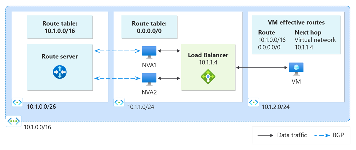
Key components
- Azure Route Server: Establishes BGP sessions and exchanges routing information
- Internal load balancer: Provides high availability and load distribution for NVAs
- Network virtual appliances: Handle traffic processing and routing functions
- Backend pool: Contains multiple NVA instances for redundancy
Traffic flow
- Route Server exchanges BGP routes with NVAs behind the load balancer
- Routes are advertised with the load balancer's frontend IP as the next hop
- Traffic destined for advertised prefixes is sent to the load balancer
- Load balancer distributes traffic to healthy NVA instances in the backend pool
Important
The internal load balancer must be deployed in the same Azure region as the Route Server. Cross-region load balancer configurations aren't supported and results in connectivity failures.
Deployment patterns
Azure Route Server's next hop IP support enables two primary deployment patterns for network virtual appliances.
Active-passive NVA configuration
Deploy NVAs in an active-passive configuration for high availability with guaranteed symmetric routing:
Architecture benefits
- Symmetric routing: All traffic flows through the same active NVA instance
- Automatic failover: Load balancer health probes detect failures and redirect traffic
- Predictable behavior: Consistent traffic paths simplify troubleshooting and security policies
Implementation approach
- Configure the internal load balancer with health probes for each NVA
- Set load balancer rules to direct traffic to the active NVA instance
- Configure BGP on NVAs to advertise routes with the load balancer's frontend IP as next hop
- Implement failover logic to promote standby NVAs when the active instance fails
Use cases
- Security appliances: Firewalls requiring consistent session state
- Deep packet inspection: Applications needing to maintain connection context
- Compliance requirements: Environments requiring deterministic traffic paths
Active-active NVA configuration
Deploy multiple active NVAs to distribute traffic load and maximize throughput:
Architecture benefits
- Load distribution: Traffic is spread across multiple NVA instances
- Horizontal scaling: Add more NVAs to handle increased traffic volumes
- Performance optimization: Parallel processing improves overall throughput
Implementation considerations
- Asymmetric routing: Return traffic might follow different paths than outbound traffic
- Session state: Applications must handle distributed or stateless processing
- Load balancer configuration: Use appropriate distribution algorithms for your traffic patterns
Use cases
- SD-WAN appliances: Distributed routing and optimization functions
- Load balancing scenarios: High-throughput applications with stateless processing
- Scalable architectures: Environments requiring dynamic capacity adjustment
Note
Active-active configurations can result in asymmetric routing patterns. Ensure your NVAs and applications can handle traffic where outbound and return paths might differ.
Configuration requirements
Implementing next hop IP support requires specific configuration on your network virtual appliances and load balancer.
NVA BGP configuration
Configure BGP on your NVAs to advertise routes with the load balancer's frontend IP as the next hop:
# Example BGP configuration for Cisco-based NVA
router bgp 65001
 neighbor 10.1.1.4 remote-as 65515
 neighbor 10.1.1.5 remote-as 65515
 !
 address-family ipv4
  neighbor 10.1.1.4 activate
  neighbor 10.1.1.5 activate
  neighbor 10.1.1.4 next-hop-self
  neighbor 10.1.1.5 next-hop-self
  neighbor 10.1.1.4 route-map SET-NEXTHOP out
  neighbor 10.1.1.5 route-map SET-NEXTHOP out
 !
route-map SET-NEXTHOP permit 10
 set ip next-hop 10.1.0.100
Load balancer configuration
Configure the internal load balancer with appropriate health probes and distribution rules:
- Health probes: Monitor NVA availability and redirect traffic during failures
- Load balancing rules: Define how traffic is distributed among backend NVAs
- Backend pool: Include all NVA instances that should receive traffic
Route Server peering
Establish BGP peering between Route Server and each NVA in the backend pool:
- Each NVA maintains individual BGP sessions with Route Server
- All NVAs advertise the same routes with identical next hop IP (load balancer frontend)
- Route Server learns duplicate routes but uses the load balancer IP for forwarding
Important
Next hop IP configuration is performed entirely within the BGP settings of your network virtual appliances. Azure Route Server doesn't require any special configuration to support this feature.
Next steps
Learn more about Azure Route Server capabilities and configuration: