Note
Access to this page requires authorization. You can try signing in or changing directories.
Access to this page requires authorization. You can try changing directories.
In this article, you learn how to deploy a hub-and-spoke topology with Azure Firewall using Azure Virtual Network Manager. You create an Azure Virtual Network Manager instance, or network manager, and implement network groups for trusted and untrusted traffic. Next, you deploy a connectivity configuration that defines your hub-and-spoke topology. When deploying the connectivity configuration, you have a choice of adding direct connectivity for trusted communication between spoke virtual networks, or requiring spoke virtual networks to communicate through the hub virtual network. You finish by deploying a routing configuration to route all traffic to Azure Firewall, except for the traffic within the same virtual network when the virtual networks are trusted.
Many organizations use Azure Firewall to protect their virtual networks from threats and unwanted traffic, and they route all traffic to Azure Firewall except trusted traffic within the same virtual network. Traditionally, setting up such a scenario is cumbersome because new user-defined routes (UDRs) need to be created for each new subnet and route tables have different UDRs among them. UDR management in Azure Virtual Network Manager can help you easily achieve this scenario by creating a routing rule that routes all traffic to Azure Firewall, except for the traffic within the same virtual network, and applying this rule easily across your spoke virtual networks.
Prerequisites
An Azure subscription with permissions to create resources in the subscription. If you don't have an Azure subscription, create a Trial before you begin.
Three virtual networks with subnets in the same region. One virtual network is the hub virtual network, and the other two virtual networks are the spoke virtual networks.
- For this example, the hub virtual network is named hub-vnet, and the spoke virtual networks are spoke-vnet-1 and spoke-vnet-2.
- The hub virtual network requires a subnet for the Azure Firewall named AzureFirewallSubnet.
An Azure Virtual Network Manager instance with user-defined routing and connectivity features enabled.
All virtual networks configured in a hub-and-spoke topology through a connectivity configuration or manually created.
An Azure Firewall in the hub virtual network. For more information, see Deploy and configure Azure Firewall and policy using the Azure portal.
Create a Virtual Network Manager instance
In this step, you deploy a Virtual Network Manager instance with user defined routing enabled.
Sign in to the Azure portal.
Select + Create a resource and search for Network Manager. Then select Network Manager > Create to begin setting up Virtual Network Manager.
On the Basics tab, enter or select the following information, and then select Review + create.
Setting Value Subscription Select the subscription where you want to deploy Virtual Network Manager. Resource group Select the resource group containing your virtual networks and firewall.
Select Ok.Name Enter name for network manager. Region Select China North 3 or a region of your choosing. Virtual Network Manager can manage virtual networks in any region. The selected region is where the Virtual Network Manager instance is deployed. Description (Optional) Provide a description about this Virtual Network Manager instance and the task it's managing. Features Select User defined routing and Connectivity from the dropdown list. 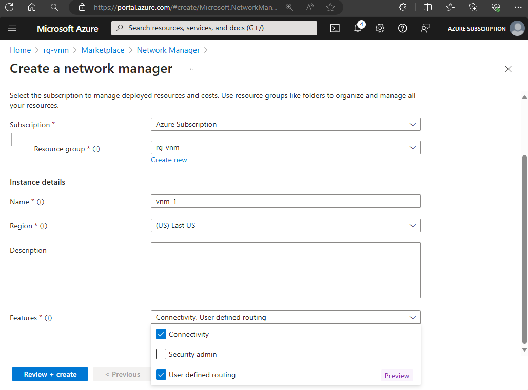
Select the Management scope tab or select Next: Management scope > to continue.
On the Management scope tab, select + Add.
In Add scopes, choose your subscription or management group, then choose Select.
Select Review + create and then select Create to deploy the Virtual Network Manager instance.
Create a network group with manual membership
In this task, you create a network group with manual membership that includes your spoke virtual networks. Network groups are used to manage multiple virtual networks in a single configuration.
In the Azure portal, select your network manager instance.
Under Settings on the left side, select Network groups and select + Create.
In the Create a network group pane, enter the following settings then select Create:
Setting Value Name Enter a name for your network group. Description (Optional) Enter a description for your network group. Member Type Select Virtual network. On the Networks groups page, select the network group you created then select Add virtual networks under Manually add members.
In the Manually add members window, select spoke virtual networks then select Add.
Important
Don't add hub virtual network to this network group. If it's added as a member, you can't create a hub and spoke topology connectivity configuration with the group. The hub is selected during the creation of the connectivity configuration.
Create a connectivity configuration
In this task, you create a connectivity configuration that includes your network group and a routing rule collection. You can choose to enable direct connectivity in the hub and spoke topology, or leave all communication to go through the hub virtual network and Azure firewall.
In the network manager instance, select Configurations under Settings then select Create connectivity configuration.
In the Create a connectivity configuration window, enter the connectivity configuration Name and Description on the Basics tab then select Next: Topology >.
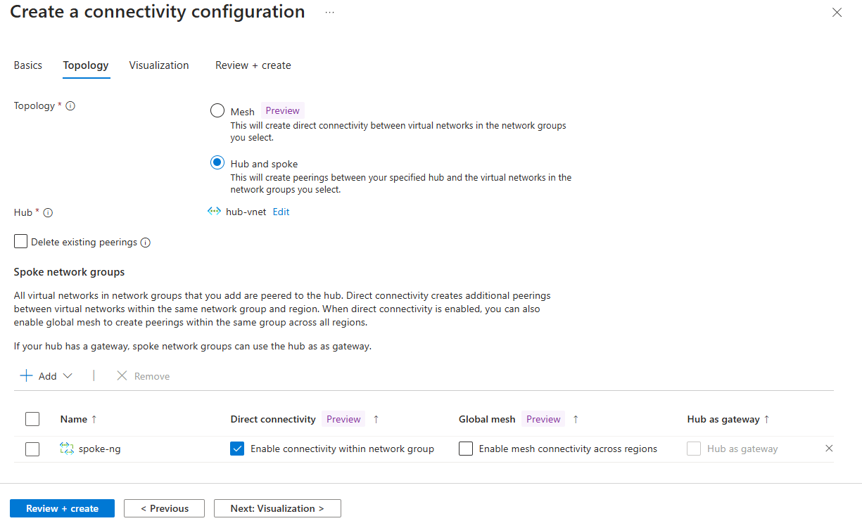
On the Topology tab, enter or select the following settings:
Setting Value Topology Select Hub and spoke. Hub Choose Select a hub.
On the Select a hub page, choose your hub virtual network then select Select.Spoke network groups Choose + Add>Add network groups.
On the Add network groups page, choose your network group then choose Select.From the list of Spoke network groups, you can choose to enable Direct connectivity or Global mesh. Direct connectivity allows spoke virtual networks to communicate directly with each other. Global mesh allows all virtual networks to communicate with each other. Leaving these unchecked results in all spoke virtual networks communicating through the hub virtual network and Azure firewall.
Important
If you enable direct connectivity, you must have a routing configuration with direct routing within the virtual network. If you enable global mesh, you must have a routing configuration with global mesh enabled.
Choose Next: Visualization > to review the connectivity configuration then select Review + create > Create.
Deploy connectivity configuration
In this task, you deploy the connectivity configuration to create the hub and spoke topology.
In the network manager instance, select Configurations under Settings then select the connectivity configuration you created.
From the task bar, select Deploy.
In the Deploy a configuration window, select the connectivity configuration you created, and select the Target Regions you wish to deploy the configuration to.
Important
The hub and spoke topology is created in the selected regions. Make sure to select the regions where your hub and spoke virtual networks are deployed.
Select Next or the Review + deploy tab then select Deploy.
Select Deployments under Settings, and verify your deployment was successful.
Create a routing configuration and rule collection
In this task, you create a routing configuration and rule collection that includes your spoke network group. Routing configurations define the routing rules for traffic between virtual networks.
In the network manager instance, select Configurations under Settings.
On the Create a routing configuration page, enter the routing configuration's Name and Description on the Basics tab, then select Next: Rule collection >.
Select Add on the Rule collections tab.
In the Add a rule collection window, enter or select the following settings for the rule collection:
Setting Value Name Enter a name for your rule collection. Description (Optional) Enter a description for your rule collection. Local route setting Select Direct routing within virtual network. Enable BGP route propagation (Optional) Select Enable BGP route propagation if you want to enable Border Gateway Protocol (BGP) route propagation. Target network group Select your spoke network group. Under Routing rules, select Add to create a new routing rule.
In the Add a routing rule window, enter or select the following settings for the routing rule:
Setting Value Name Enter a name for your routing rule. Destination Destination type Select IP Address. Destination IP Addresses/CIDR ranges enter 0.0.0.0/0. Next hop Next hop type Select Virtual Appliance.
Select Import Azure firewall private IP addressAzure firewalls Select your Azure firewall then choose Select. Select Add to add the routing rule to the rule collection.
Select Add to add the rule collection to the routing configuration.
Select Review + create then select Create.
Deploy the routing configuration
In this task, you deploy the routing configuration to create the routing rules for the hub-and-spoke topology.
- In the network manager instance, select Deployments under Settings.
- Select Deploy configurations then select Routing configuration - Preview.
- In the Deploy a configuration window, select the routing configuration you created, and select the Target regions you wish to deploy the configuration to.
- Select Next or Review + deploy to review the deployment then select Deploy.
Delete all resources
If you no longer need the resources created in this article, you can delete them to avoid incurring more costs.
- In the Azure portal, search for and select Resource groups.
- Select the resource group that contains the resources you want to delete.